Downconversion and Frequency Tuning
Background
EOVSA has three consecutive frequency-conversion operations required to tune and isolate a clean 500 MHz IF band from the 1-18 GHz RF band. The first is a tunable upconversion to a 20-20.5 MHz band, which is filtered but with a rather gentle roll-off due to the high center frequency. The second is a fixed-frequency downconversion of the 20-20.5 MHz band centered on a sharply filtered IF bandpass from 600-1200 MHz. The third downconversion is that due to the digitizer, whose nominal clock is 1200 MHz, although for practical reasons during the prototype phase we are operating the digitizer at a sub-optimal 800 MHz clock speed. This document describes these frequency conversions and the resultant ordering of frequency channels in the digitized data, both for the production unit with a 1200 MHz digitizer clock, and for this interim period with an 800 MHz clock. We demonstrate that the system corresponds to our expectations by introducing a frequency-swept CW signal into the IF path and observing its effects. We also discuss the linearity of the system, which probably belongs in a separate memo.
Tuning and First Frequency-Conversion
Figure 1 shows the basic tuning operation for four different IF bands. Each tuning inverts the 1-18 GHz RF by mirroring it around the LO frequency. To tune to each of the 500 MHz between 1-18 GHz, 34 tunings are required ranging from 21.5 GHz to 38 GHz. The RF frequency at the low end of the 500 MHz band is related by the LO frequency by 20.5GHz. In the figure, the RF frequency scale is shown in black, and the IF frequency scale (after the conversion) is shown in blue. As the LO frequency changes, the mirrored RF band slides to the right with twice the step of the LO frequency change, while the fixed 20-20.5 GHz filter slides to the right with the same step as the LO. Thus, the mirrored RF slides past the filter window at the same rate as the LO frequency change. Note that the RF frequencies are inverted due to the mirroring.
Second Frequency-Conversion
In order to digitize the signal, the high-frequency IF must be converted to a lower frequency. To accomplish this, the EOVSA system mixes the fixed 20-20.5 GHz signal with a fixed 21.15 GHz second LO as shown in Figure 2, whose format is similar to that of Figure 1. The rather gentle roll-off of the 20-20.5 GHz filter is indicated by the sloping sides of the bandpass. Again, the original frequency scale is shown in black, and the mirrored copy of the bandpass is shown in blue, labeled with its lower IF frequency scale in MHz, also in blue. This IF bandpass shape is then filtered with a sharply defined IF filter from 600-1200 MHz (outer dashed lines marked as Digitized Bandpass). This second mirroring of the band causes the previously inverted RF frequencies to again have a direct ordering.

Digitization and the Third Frequency-Conversion
This second IF band is now at a sufficiently low frequency for digitization. For the final production system, EOVSA’s correlator will digitize the signal using a 1200 MHz clock. This action will mirror the IF a third time, as shown in Figure 3. The clock frequency is 50 MHz above the desired band, and the passband of the filter is 100 MHz narrower than the 600 MHz nyquist bandwidth of the clock, so that the skirt of the filter roll-off, which is aliased back into the passband, is reduced by 63 dB below the desired signal. The 600 MHz digitized passband is shown in green, but the target passband is the narrower 500 MHz band indicated between 50 and 550 MHz. Because the correlator F-engine produces 4096 channels over 600 MHz, the actual desired data will be found in channels 341-3755. For the production system, then, this third mirroring of the RF will result in an inverted order of frequency channels, but with the fortunate advantage that this inversion never changes--it does not depend on the RF band to which the system has been tuned.

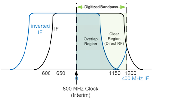
Unfortunately, it has been necessary to temporarily restrict the digitizer clock during the prototype phase to 800 MHz (an FPGA clock speed of 200 MHz), which provides a nyquist bandwidths of only 400 MHz. Figure 4 shows the impact of this non-ideal clock speed on the digitized band.

Clearly the resulting data are compromised, because the lower half of the 400 MHz bandwidth is contaminated due to the 200 MHz range from 600-800 MHz being folded onto the 800-1000 MHz band. Only the 1000-1200 MHz range of the filtered second IF will be clean, and will be downconverted to the 200-400 MHz IF range. Note also that the 800-1200 MHz range of the filtered second IF will have direct RF ordering, while the mirrored 600-800 MHz range will have inverted ordering.
As of 2016 October 15, Jack Hickish says that a 300 MHz FPGA clock speed may not be possible. An ADC clock speed of 1120 MHz (ADC clock speed 280 MHz) may be possible, which would result in the situation shown in Figure 5. Note that the RF is inverted in the IF band.


